TUBE BUFFER
Croatian version
(6 December 2007)
Since this article is in the section for 'noobs', we'll leave the 'heavy' stuff for another time and focus here on a straightforward presentation of a simple tube buffer design, such that it may serve as an easy introduction for any novice to the world of the vacuum and free electrons.
The design laid out below is quite flexible as it allows users to experiment with different vacuum tubes (or 'valves' to all those Brits out there), operating points and active and passive parts while, at the same time, it does not require any particular in-depth knowledge of either tubes or audio electronics in general. To make things even more 'newbie-friendly', I have made a special effort to explain all necessary calculations in very simple, common-sense terms, free of jargon or tedious academic mystification. With this in mind, it should be clear that the tube buffer topology presented here is by no means intended to be taken as the be-all and end-all of tube design but rather as an educational project with very tangible practical value and a good starting point for more complex circuits and further learning.
So, what is the buffer good for?
A tube buffer, also known as a voltage or cathode follower, is a circuit whereby the high output impedance of the source is lowered so that it can be properly transferred to the lower input impedance load. The tube buffer has no voltage gain. It has current gain and, therefore, power gain. In audio electronics, it is normally used when our amplifier has enough gain but we still need a volume control with low output impedance.
Vacuum tubes are primarily voltage amplifiers so they do not work particularly well under large current loads. Where there is only one active device (tube) in single-ended mode, like here, excessive output current will always result in higher harmonic distortion. Speaking of distortion, it should be noted that a properly implemented tube buffer will normally generate very little harmonic distortion, which will be predominantly even-order and which in combination with predominantly odd-order harmonic distortion generated by simple push-pull amplifiers (based on chips, like gainclones and such, for instance) may make the overall sound of the system more palatable to the ear. In my personal experience, chip amplifiers with tube buffers have consistently sounded more tonally balanced ('natural'), plausible, 'musical' (coherent, if you will) and, overall, subjectively more enjoyable than without them or in combination with other types of preamplifiers or attenuators.
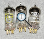
Triodes
Low-power triodes are a good choice for this project because of the simplicity of their implementation, low output impedance, solid linearity without the use of negative feedback, etc. A triode is a vacuum (i.e. electron) tube which has three electrodes: the cathode, the anode and the grid. When hot, the cathode emits electrons into the surrounding vacuum and the anode attracts them with its high positive potential while the grid determines how many electrons will be attracted by the anode (thus regulating the anode current). Because the power on the grid used to modulate the anode current is much lower than the power generated by modulation, so we get an amplifier, which is characterized by the following parameters: gain, transconductance and output impedance. These parameters may vary to a certain extent depending on the operating point chosen, so the characteristics of a specific triode will be most easily determined from the graph of its output characteristics. To exemplify this point, let us look at the output characteristics of the ECC88, a double (twin) triode tube made by JJ Electronic, shown in the graph below.
The output/anode characteristic in the graph shows the relationship of output/anode current (the vertical axis or ordinate) to anode voltage (the horizontal axis or abscissa) for several different grid biases. From the graph, we can determine the gain, transconductance and output impedance of the triode and even predict the level of its harmonic distortion. Some of these parameters will also depend on the load of the triode and its output voltage, as will be exemplified with reference to operating point A.
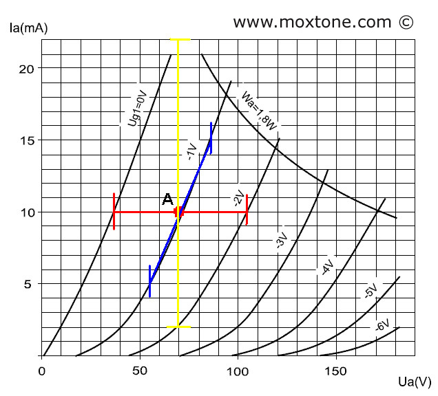
For operating point A, the following data is derived from the above graph:
Ia=10mA, Ua=70V and Vg=-1V.
The gain of the triode can be determined by drawing a horizontal line (shown in red color) through operating point A, starting and ending with the two adjacent curves - the one on the left and the one on the right (for Vg1=0 and Vg2=-2V). The values for the anode voltage (Va1=35V and Va2=105V, respectively) are then read on the horizontal axis. Finally, the gain of the triode is calculated by dividing the anode voltage difference by the grid voltage difference, as in the following equation:
mu=(105-35)/(2-0)= 70/2=35.
The rated value supplied by the manufacturer is mu=33.
In simple terms, to determine the gain (mu) for a specific operating point, we need to measure the anode voltage difference in reference to the given grid voltage difference.
The transconductance of the tube can be determined by drawing a vertical line (shown in yellow) through operating point A. On the vertical axis, we then read the respective values of anode currents where the vertical line intersects the adjacent grid curves (for Vg1=0 and Vg2=-2V). In this case, the values are Ia1=22mA for Vg1=0 and Ia2=3mA for Vg2=-2V. Transconductance S is calculated by dividing the anode current difference by the grid voltage difference:
S=(22-3)/(2-0)=9.5mA/V .
The rated value supplied by the manufacturer is S (gm)=12.5mA/V. Our result is somewhat below the rated value because it contains also the non-linear part of the characteristic (from point A downward).
Internal resistance Ri can be determined by drawing a line (shown in blue) through operating point A along the tangent of its curve. For a symmetrical change of the anode current (5mA up and 5mA down), we determine the corresponding anode voltage change. When these two values are divided (dVa/dIa), we get Ri. In this case, we get:
Ri=(85V-55V)/(15mA-5mA)=3kΩ.
The rated value Ri is 2.6kΩ.
Mathematically, the relationship between the three aforementioned parameters can be simply expressed as:
mu=S*Ri.
Load line
The calculated mu value is a theoretical value, which is based on the assumption that the anode current does not change (i.e. that it is constant). However, this assumption would hold true if the tube were not connected to any load, which in reality is clearly not the case. All output amplifiers have some (not infinite!) input resistance, which must be factored in our calculations. To do that, we will draw several load lines for our operating point, as shown in the picture below.
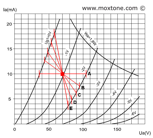
Load line B represents load Rl=10kΩ, load line C is for Rl=5kΩ, load line D is for Rl=2.5kΩ and load line E represents Rl=1.4kΩ. We can also draw more lines for other loads. The slope of the line is determined by calculating the corresponding change in anode voltage for a known current change, using Ohm's Law, according to the following formula:
dVa=dIa*Rl .
The resulting line is then plotted through the desired operating point. Looking at the load lines, two main conclusions can be drawn. The first is that a decrease in the load also decreases the gain mu. For example, for load line D, the gain is only 15!!
The second conclusion is that anode voltage swings are not the same for the corresponding variations in grid voltage with respect to the operating point. Looking at load line D, the grid voltage change from Vg =-1V to Vg = 0V results in the anode voltage swing dVa of 17V, whereas the grid voltage change from Vg =-1V to Vg =-2V results in the anode voltage swing dVa of 13V. This asymmetry is the cause of harmonic distortion, which leads us to the obvious conclusion that distortion increases with higher load levels because in one half-period the load line will run deeper into the non-linear part of the transfer characteristic.
Operating point selection
The selection of operating point depends on several factors, the most important being the class of operation, maximum anode voltage swing (the length of the load line) and the size of the load (the slope of the load line). The picture below shows several operating points and possible load lines for each of them.
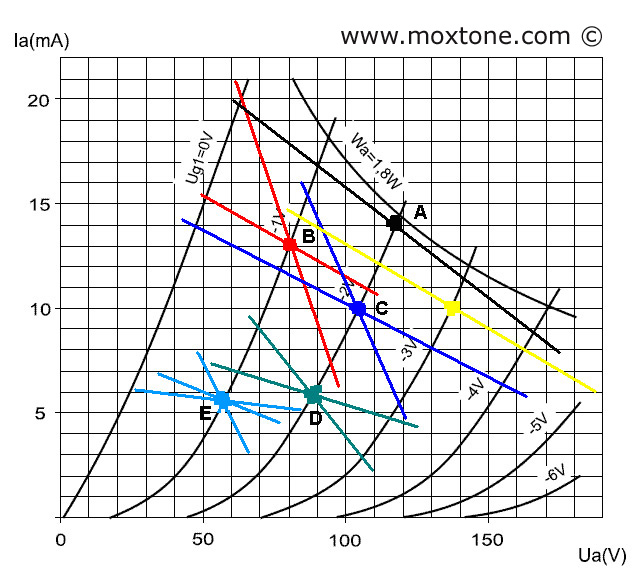
Operating point A (black or yellow line) will be used when a large signal amplitude is required, such as when a triode with a large gain is used as the voltage amplifier stage (VAS) of an output power amplifier. The load line is placed in the most linear part of the characteristic so as to minimize distortion as much as possible. However, the load that the triode is now seeing is at its peak, which may reduce the lifespan of the tube dramatically. And if the load increases even further (for example, due to its reactive components), the load line may easily overshoot the allowable dissipation (1.8 W), consequently overheating and destroying the triode.
Operating points B and C are in, arguably, the optimal operating area of the triode under discussion. The linear area for the required signal amplitude is large enough, the dissipation is manageable and the tube's longevity is guaranteed. This is also the area which is commonly used in preamplifiers and similar applications and it is the reference area for which the manufacturer rates the triode. It is thus no wonder that many audio designers and audiophiles swear that the ECC88 sounds best with the operating point set in this very area.
Operating points D and E will be the option of choice when a low signal amplitude is required, when the triode load is low (but higher than 10kΩ in order to ensure linearity and minimize distortion) and when only a limited supply voltage is at our disposal (as from the power supply of a transistor amplifier, for instance). These operating points are useful when designing a buffer with a low signal amplitude (a few volts) and small load (10-100kΩ), like the one discussed here.
OK, this is just enough theory for you to be able to get your soldering iron all hot and ready for action.
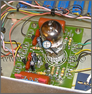
Implementation
Here, I am setting the operating point at the edge of areas B-C and D-E. The anode current is 10mA for the anode voltage of Va=70V and the grid voltage of Vg=-1V. The schematic of the buffer is shown in the figure below.
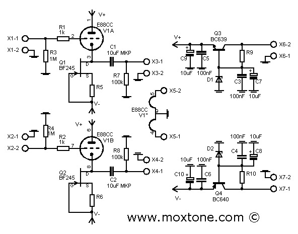
To bring the triode to the desired operating point, we shall use a current source consisting of one N-channel JFET BF245C and the respective source resistor. The main rationale for using the current source is that it presents infinite resistance to the AC signal. The larger the resistor, the better the linearity of the circuit, as already shown in the operating point analysis. In practice, however, the resistance of the current source is not really infinite but large enough. If you take a look at the output characteristic of the JFET shown in the figure below,
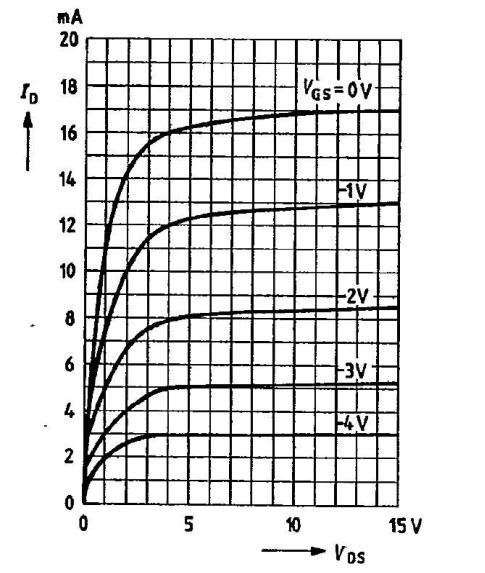
you will see that the current (Id) in the voltage range (Vds) from 5 to 15V increases by about 0.5 mA, allowing us to estimate that the dynamic resistance of the current source would be approximately 20kΩ. To be able to achieve such dynamic resistance and the current Ia of 10mA, using only one resistor, we would need to have an additional negative voltage of 200V!! However, with the current source, the voltage of-15V will do the trick just as nicely.
 Furthermore, in order to get the current of 10mA, the bias voltage at the gate of the JFET should be approximately -1.5V. Ohm's Law tells us that the value of R5 and R6 is about 150Ω. Due to considerable non-uniformity in JFET characteristics, the value of R5 and R6 will in practice need to be further adjusted to get the current of exactly 10mA. The adjustment is most easily done by replacing both resistors with trimmers of about 250Ω each and then adjusting the resistance of each trimmer until the current reads 10mA. Then the exact value of each trimmer's resistance is measured and the trimmers are replaced with fixed resistors (R5 and R6) of the measured value. Here, it should be noted that BF245 JFET transistors with the C suffix, which indicates a drain saturation current (Idss) higher than 10mA, must be used. In the absence of such a transistor, two BF245B connected in parallel may be used, or any other N-channel JFET with Idss greater than 10mA.
The grids of the triodes are set to zero potential via resistors R3 and R4 (there is no need for an input coupling capacitor) whereas the negative bias with respect to the cathode is obtained automatically by forcing the current of 10mA through the triode and the JFET. It may happen that the negative bias is not exactly Vg =-1V, depending on the characteristics of the triode, manufacturer and, to a certain extent, condition of the tube itself. And here is another strong point of the current source: it inherently keeps the triode at the same operating point all the time, which is not the case with some other biasing methods.
In normal operation, the cathode is at the positive potential equal to the bias voltage of the triode, which is 1V in this particular case. The cathode (which is the output of the buffer) should, therefore, be connected via decoupling capacitors C1 and C2 to the output jacks. The value of the capacitors will depend on the load of the subsequent stage (usually, input resistance of a power amplifier). However, its minimum value can be approximately calculated as:
C=1/(62.8*R).
In the above calculation, the output impedance of the triode is ignored whereas the corner frequency is fHP = 10Hz. Thus, for instance, for R=10 kΩ, we get C=1.6 µF.
For safety reasons, the operating voltage of the capacitor should be greater than the anode voltage. So, even though the value of the capacitor used in the actual build is in fact C1=3µ3/100V, its value in the schematic is set to 10µF, just to be on the safe side.
The supply voltage of the buffer is +70 /-15V. The PCB accommodates two simple regulators, each consisting of a series transistor and a Zener diode as a reference. The voltage at the input of the regulators should be at least 5V greater than their output voltage (or, in this particular case, +75 /-20V). For the anode voltage regulator, you need a Zener diode of 70V, 0.5 W. The value of resistor R9 is calculated according to the formula:
R9=(Vin-Va)/Izd=(75-70)/0.003=1666Ω.
(Note: in reality, the closest standard resistor value is selected, which is 1500Ω in this case).
To stabilize negative voltage, a Zener diode of 15V, 0.5W should be used. The value of resistor R10 is calculated as follows:
R10=(Vin-V-)/Izd=(20-15)/0.005=1kΩ.
The rated voltages of the capacitors (for both, positive and negative power supply) should be higher than the voltage of the rectifier so here we should use 100V capacitors for the anode voltage regulator and 25V capacitors for the negative voltage regulator.
Power supply
Power supplies for tube gear tend to be quite complex and may even require scarcely obtainable and non-standard parts. To spare you unnecessary headaches, I hereby propose, for a change, a simple power supply design with readily available and inexpensive parts. The schematic is shown in the figure that follows.
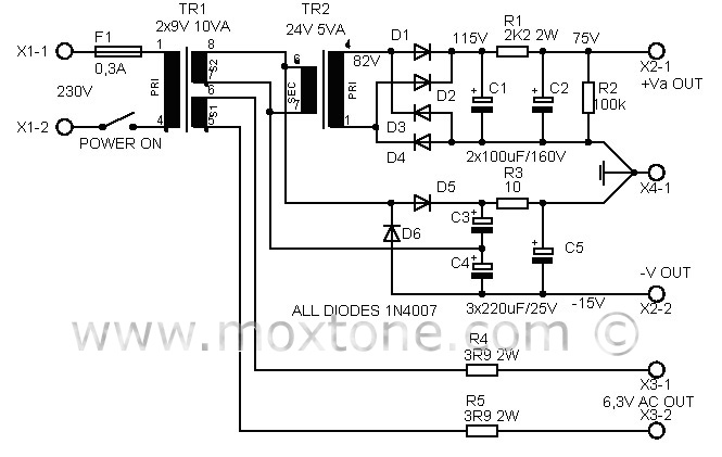
The central part of the power supply is a small power transformer (EI or toroid) with two 9V secondaries and the output power of 10VA. One secondary is used to power the tube filaments via resistors R4 and R5, which reduce the heating voltage from 9 to 6.3 V, as well as current inrush on the cold heaters of the triode at power-on. Since tubes from different manufacturers may have different nominal heating currents, you will likely have to determine experimentally the best value of resistors R4 and R5. You will do so by checking the heater voltage when the buffer is turned on and then adjusting the resistors until you get 6.3V. Thus, the value of the resistors in the schematic is 3.9Ω, which corresponds to the heating current of 0.365A.
Perhaps some of you reading this article may wonder why not use stabilized DC voltage for heating. The answer is simple: a buffer is a circuit with unity gain and as such has no parts sensitive to AC voltage. Secondly, the filament insulation of indirectly heated triodes is far better at 50Hz than at high-frequencies that may appear in low-quality rectifiers and stabilizers (and there are a plenty of those floating around).
 The other transformer secondary output is used to power the anode and additional negative voltage rectifiers. The anode voltage rectifier consists of a small 220V/24V power transformer connected backwards, and the accompanying rectifier circuitry. The voltage of 9V is thus transformed upwards to become 80V. The rectification gives a C1 capacitor voltage of about 115V, which is then additionally filtered by the RC network and brought down to the required 75V. Should the operating voltage significantly deviate from this value (75V), it needs to be set right by adjusting the value of resistor R1. Please note that a voltage higher than 75V may overheat the stabilizer transistors while too low a voltage can reduce or shut down voltage stabilization.
The additional negative voltage is obtained by means of a voltage doubler, which in this case consists of diodes D5 and D6, capacitors C3 and C4 and RC network R3-C5. The voltage at the output of this rectifier has a value of about -18V, which is enough to drive the buffer. Naturally, there are many ways to build a power supply, depending on parts and financial resources available to you, as well as your own needs, creativity, inspiration and perspiration. The example shown here is a novice-friendly version, which has been tried and tested in practice and found to work perfectly and in full compliance with this project's requirements.
Conclusion
The purpose of this article was to provide a simple tube buffer design, along with theoretical explanations and mathematical calculations necessary to make either an exact copy of this project or any of its variants with other suitable tubes and parts. In a manner of speaking, you have been both given a fish and taught how to fish, to boot. Hopefully, the article will also light a few bulbs with regard to other similar designs and projects presented earlier on this website, such as Tube-buffered Gainclone and ECC86 preamplifier. In the concluding paragraphs that follow, we will end this fishing expedition with some final measurements and a snippet or two of possibly useful subjective impressions for future builders.
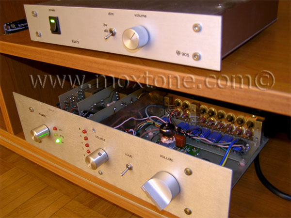
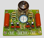
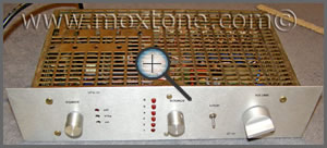
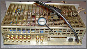
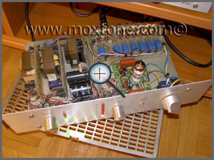
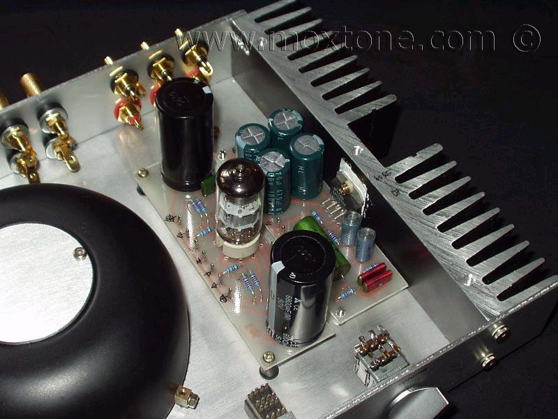
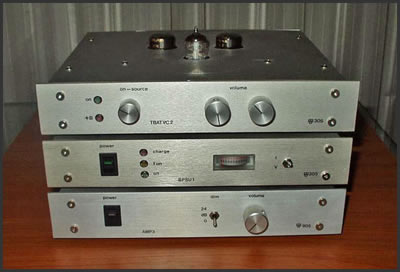
I placed the buffer inside an old metal box that originally contained an industrial SPS, which was later on (some 10 years ago) cannibalized to make space for an SRPP tube preamplifier of mine. Now I only had to adjust high voltage and heating, add negative voltage, rewire the insides and the buffer was ready to be fired up. All in all, it was no more than an hour or two of work.
 |
 |
 |
 |
After warm-up, first measurements of the buffer were made, with the following results:
- amplification, A=0.98
- frequency range, (Vout=1VRMS, +/- 0.5dB) 15Hz - 250kHz
- THD, (1kHz, Vout=1VRMS) THD=0.05%
- signal-to-noise ratio, SN=65dB
- output impedance, Rout=70Ω
- maximum input-output signal, Voutmax=10Vpp.
The resulting measurements are expectedly good. We have a buffer which works like... well, a buffer: it has unit gain, low distortion, large frequency range, large signal amplitude (due to JFET current source bias) and low output impedance. The output impedance of the buffer can also be approximated from the transconductance of the triode, according to the following formula:
Rout=1/S,
which in our case, where S = 12mA/V, gives Rout of 84Ω. So, the actual measured result turned out to be even better than the earlier theoretical predictions. Well, isn't this nice...
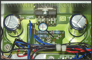
 The sound of the LM3875 (IGC) with this buffer left me (and the company present) dumbfounded at first. In disbelief, I even decided to change the loudspeakers, attributing the unexpectedly good sound to my AMT-based Slavooy speakers. But, after the change, the sound remained surprisingly good: open, dynamic, defined, detailed, clean, smooth and full-blooded. To my ears, the earlier TBIGC project was already a significant improvement over the "naked" chip, but this was definitely it.
So, if you can solder a bit and you appreciate good sound but money is on the tight side, I honestly believe that this buffer in combination with the LM3875 chip amp is right up your alley. However, since the tube is the only active element in the signal path here, it is very important for the best possible sound that you do not skimp on its quality. In my experience, you are unlikely to go wrong with Telefunken, Mullard, Siemens or Amperex PQ tubes while most other brands of ECC88 proved to be more of a sonic trade-off than I really cared for.
Related articles: |
|||
|
|||
|
|
|
|
 Visitors since 30 Aug. 2010
COPYRIGHT NOTICE
This material is not public domain. It is provided for your personal use only and may not be reproduced, re-distributed, re-transmitted, copied or otherwise used in any form without the express written permission of the author. You may not upload this material to any public server, on-line service, network or bulletin board without the prior written permission of the author.
The use or copying of the contents of this page, in whole or in part, for any commercial purpose is expressly prohibited.